In the summer 2017 my wife and I furnished our bedroom with new furniture. The new wardrobe has now LED lightning and the bed has also lightning integrated. But the bed has only one switch for the two LED’s. Switching the LED right and left separately was not possible and switch the wardrobe LED’s off while in bed was not possible. I doesn’t want a simple solution. I want something switchable with the smartphones. Because I’ve experience with the ESP8266 from my water level gauge I decide to build a switch for smartphones.
I want make use of the MQTT protocol. It’s lightweight enough to implement into a small device like the ESP8266.
The hardware
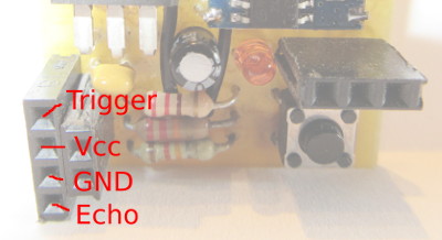
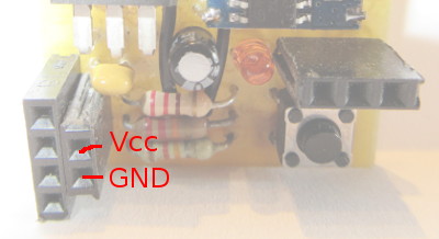
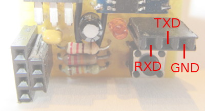
The LED’s are supplied via a 12 volt transformer. The ESp8266 needs 3.3 volts. So I decided to use a LF33CV for a stable 3.3 volts supply. For switching the LED’s I use a BD237 transistor.
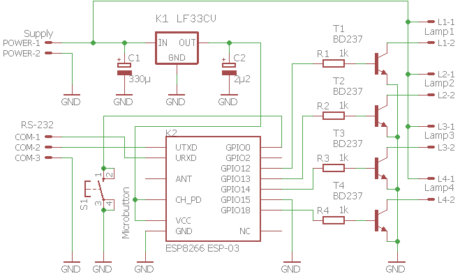
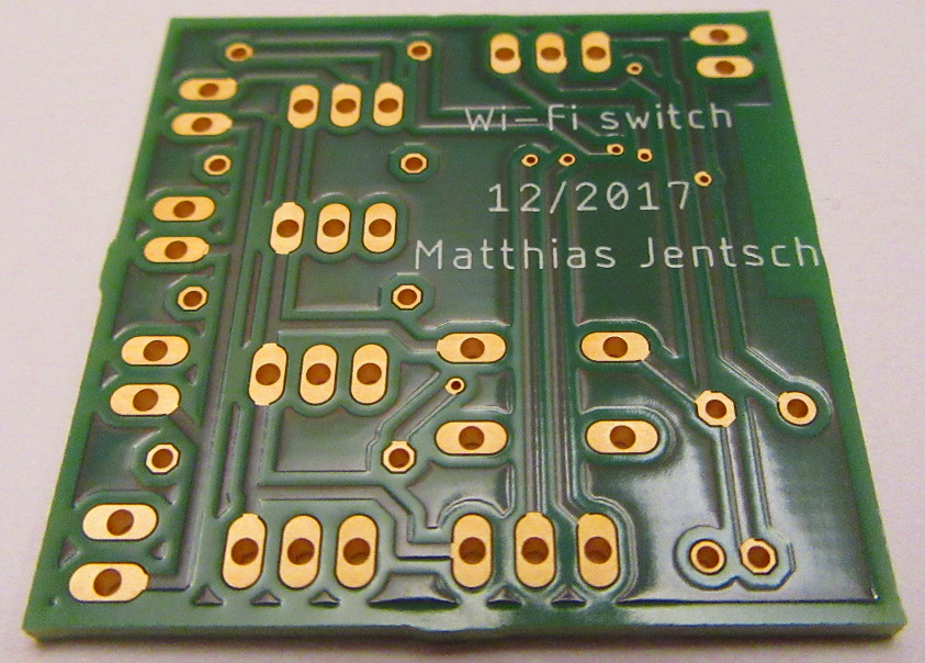
From this schematics I’ve designed a small double layer PCB.
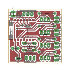
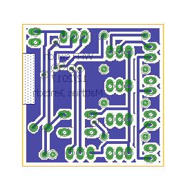
I’ve packaged the eagle schematics and board into a zip file: MqttSwitch
I’ve ordered three PCB on aisler.net and after a few day I had three professional manufactured PCB’s in hand.
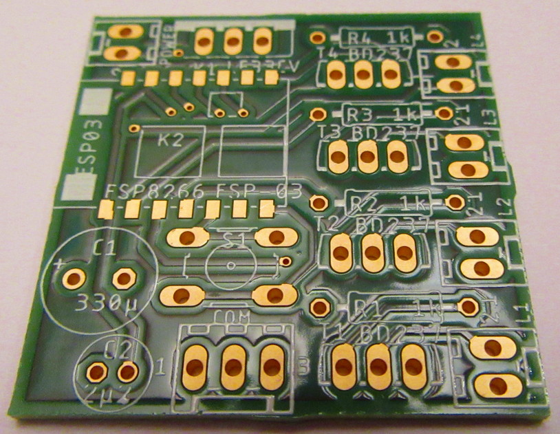
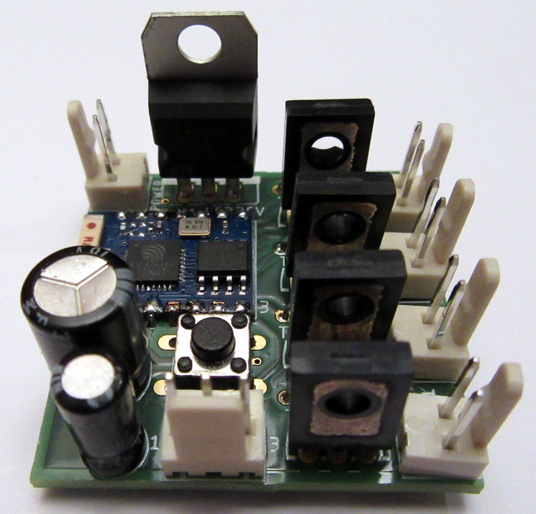
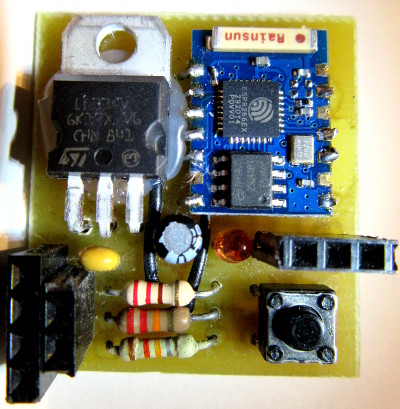
With all the parts soldered on the PCB it looks like this.
The software
Before this project I was not a big fan of the adruino develepment environment. But I’ve found that are many libraries out there for supporting the ESP8266 in general and also the MQTT protocol on the ESP8266. So I used this setup:
- adruino 1.8.5 IDE: https://www.arduino.cc
- The ESP8266 adruino extension: http://arduino.esp8266.com/stable/package_esp8266com_index.json
- The PubSubClient for adruino: https://pubsubclient.knolleary.net/
- The FadeLed: https://github.com/septillion-git/FadeLed
The LED’s are fading in and out within two seconds. That’s adjustable by FADING_TIME. The connection to the MQTT server can be established secure or unsecure. You can change the secure / unsecure setting with the defines UNSECURE_MQTT / SECURE_MQTT at the top of the sketch. And here is the complete sketch:
/*
 MqttSwitch
 Matthias Jentsch - April 2018
*/

#define UNSECURE_MQTT
//#define SECURE_MQTT

#include <ESP8266WiFi.h>
#include <ESP8266WiFiMulti.h>
#include <PubSubClient.h>
#include <time.h>

#include <FadeLed.h>
#define FADE_LED_PWM_BITS 10
#define FADING_TIME 2000

// Update these with values suitable for your network.
#define wifi_ssid1 "...................."
#define wifi_password1 "...................."
#define wifi_ssid2 "...................."
#define wifi_password2 "...................."

// MQTT connection
#define mqtt_server "...................."
#define mqtt_port 1883
// mqtt account
#define mqtt_username "...................."
#define mqtt_password "...................."
#ifdef SECURE_MQTT
// certificate fingerprint
#define mqtt_server_fingerprint ".. .. .. .. .. .. .. .. .. .. .. .. .. .. .. .. .. .. .. .."
#endif

// Constants for wardrobe switch
/*#define MAX_LAMPS 4
#define LAMP1_PIN 12
#define LAMP2_PIN 13
#define LAMP3_PIN 14
#define LAMP4_PIN 16
const int LAMP_PINS[] = {LAMP1_PIN, LAMP2_PIN, LAMP3_PIN, LAMP4_PIN};
FadeLed lamps[] = {LAMP1_PIN, LAMP2_PIN, LAMP3_PIN, LAMP4_PIN};
#define mqtt_clientName "SwitchWardrobe"
#define mqtt_topic "switchWardrobe"*/

// Constants for bed switch
#define MAX_LAMPS 2
#define LAMP1_PIN 12
#define LAMP2_PIN 13
const int LAMP_PINS[] = {LAMP1_PIN, LAMP2_PIN};
FadeLed lamps[] = {LAMP1_PIN, LAMP2_PIN};
#define mqtt_clientName "SwitchBed"
#define mqtt_topic "switchBed"

// WiFiClient for multiple access points
ESP8266WiFiMulti wifiMulti;
#ifdef UNSECURE_MQTT
// unsecure connection
WiFiClient espClient;
#endif
#ifdef SECURE_MQTT
// secure connection
WiFiClientSecure espClient;
#endif
PubSubClient client(espClient);

void setup() {
  // Initialize the LED pins as outputs
  for (int i = 0; i < MAX_LAMPS; i++) {
    pinMode(LAMP_PINS[i], OUTPUT);
  }
  Serial.begin(115200);
  // switch LEDs off
  delay(10);
  for (int i = 0; i < MAX_LAMPS; i++) {
    digitalWrite(LAMP_PINS[i], LOW);
    lamps[i].setTime(FADING_TIME);
  }
  setup_wifi();
  client.setServer(mqtt_server, mqtt_port);
  client.setCallback(callback);
}

void setup_wifi() {
  // We start by connecting to a WiFi network
  Serial.println();
  Serial.print("Connecting to access point");
  WiFi.mode(WIFI_STA);
  wifiMulti.addAP(wifi_ssid1, wifi_password1);
  wifiMulti.addAP(wifi_ssid2, wifi_password2);
  while (wifiMulti.run() != WL_CONNECTED) {
    delay(500);
    Serial.print(".");
  }
  Serial.println();
  Serial.printf(" connected to %s\n", WiFi.SSID().c_str());
  Serial.println("IP address: ");
  Serial.println(WiFi.localIP());

#ifdef SECURE_MQTT
  // Synchronize time useing SNTP. This is necessary to verify that
  // the TLS certificates offered by the server are currently valid.
  Serial.print("Setting time using SNTP");
  configTime(8 * 3600, 0, "pool.ntp.org", "time.nist.gov");
  time_t now = time(nullptr);
  while (now < 1000) {
    delay(500);
    Serial.print(".");
    now = time(nullptr);
  }
  Serial.println("");
#endif
}

void callback(char* topic, byte* payload, unsigned int length) {
  Serial.print("Message arrived [");
  Serial.print(topic);
  Serial.print("] ");
  for (int i = 0; i < length; i++) {
    Serial.print((char)payload[i]);
  }
  Serial.println();

  if (String(topic) == mqtt_topic) {
    for (int i = 0; i < MAX_LAMPS; i++) { if (length > i) {
        Serial.print("Lamp");
        Serial.print(i + 1);
        if ((char)payload[i] == '0') {
          lamps[i].off();
          Serial.println(" off");
        }
        else if ((char)payload[i] == '1') {
          lamps[i].on();
          Serial.println(" on");
        }
        else {
          Serial.println(" unchanged");
        }
      }
      else {
        break;
      }
    }
  }
  else {
    Serial.println("Unknown topic!");
  }
}

void reconnect() {
  // Loop until we're reconnected
  while (!client.connected()) {
    Serial.print("Attempting MQTT connection...");
    // Attempt to connect
    if (client.connect(mqtt_clientName, mqtt_username, mqtt_password)) {
      Serial.println("connected");
#ifdef SECURE_MQTT
      if (espClient.verify(mqtt_server_fingerprint, mqtt_server)) {
        Serial.print("verified tls!");
      } else {
        Serial.print("unverified tls");
      }
#endif
      // resubscribe
      client.subscribe(mqtt_topic);
    } else {
      Serial.print("failed, rc=");
      Serial.print(client.state());
      Serial.println(" try again in 5 seconds");
      // Wait 5 seconds before retrying
      delay(5000);
    }
  }
}

void loop() {
  if (!client.connected()) {
    reconnect();
  }
  client.loop();

  FadeLed::update(); //updates all FadeLed objects
}
 After
After 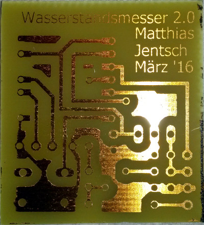 The
The