 After my first steps with the ESP8266 I got far beyond a hello world application. I’ve replaced my old self-made water level gauge with a new self-made one powered by an ESP8266 SoC. The old one have an ultrasonic sensor that sits in my cistern. The sensor was driven by an AT89C4051 micro controller with also controls a big 4-digit 7-segment display.
The new one has also the same HC-SR04 ultrasonic sensor that sits in the cistern. The measurement of the water level is now driven by the ESP8266. But the water level is now send via my router to the internet platform Thingspeak. I’ve a channel in Thingspeak where I can record the measured values.
I’ve started my development with the esp-open-sdk build environment on top of an ubuntu 15.04 server. After I got the blink example running I’ve ported my already existing c code for measuring the water level from the AT89C4051 to the ESP8266. That was the easiest task. Next I integrated the esphttpclient from Martin d’Allens into my project. Thanks Martin for the nice piece of code.
After that I could measure and post the values to Thingspeak. But I’d a big problem. The current consumption. I would power the my Internet-of-Things device by solar energy. So I connected the two pads on the PCB to get the deep sleep feature running.
The device is now powered by a cheap solar accu pack. Most of the time the device is sleeping. I wakes up regular with Wi-Fi modem deactivated to save power. Then it measured the water level and compares the values with the last measurement. If the measured value has not changed too much then the data should not be posted to save power. But after a configurable time span the data will always posted, even if not changed.
That brings me to the next point: the configuration. At the beginning I’d all parameters hard-coded. But I would configure the device via Wi-Fi. I the device is running (not sleeping) I can press the button for at least two seconds to enter the configuration mode. The module signals the configuration mode by blinking slowly with the LED. In configuration mode the ESP8266 is in SoftAP mode with a fixed SSID and a fixed password. It has a fixed IP address and opens a fixed TCP server port. Now a smart phone can send the configuration data as JSON to this port. I use the free of charge Android app TCP client for the configuration. After the ESP8266 has received the configuration it starts with measurement and sending the data to Thingspeak.
I’ve released the source code under the MIT License on github. The binaries for the version 0.1 for the 512KB flash version only can be found also on github.
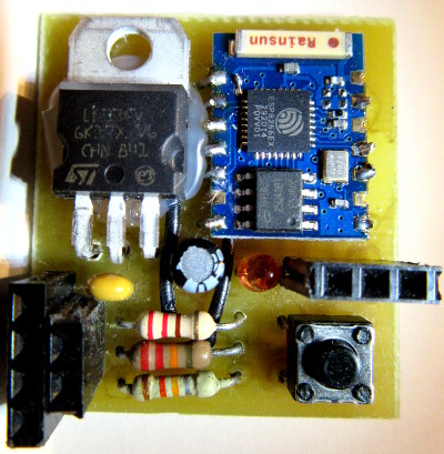
Assembling the hardware
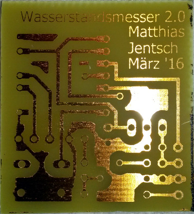 The schematics and the board layout are created with EAGLE. I’ve decided to make a single sided board to make it easy to manufacture the PCB at home. For the hardware you need the following parts:
- ESP8266 – ESP-03
- Regulator LF33CV
- LED 3mm red
- Capacitor 2.2µF
- Capacitor 100nF
- Resistor 220Ω
- Resistor 12kΩ
- Resistor 22kΩ
- Micro button
- 4-pin header
- 3-pin header
- 2-pin header
- USB Solar accu pack
With the board layout file you can create the PCB by your own or order the PCB via internet. After drilling the holes I suggest the assembling in the following order:
- Solder the two wires on top of the PCB
- Don’t forget connecting the two pads on the PCB of the ESP-03 for the deep sleep function to work
- Place the ESP-03 on top of the PCB and solder two opposite pins with a short connection between the bottom layer and the ESP-03 PCB
- Solder the rest of the pins of the ESP-03
- Solder the three resistors and the two capacitors; consider the polarity of the 2.2µF capacitor
- Continue with the LED, the micro button and the regulator
- Solder the header connectors at last
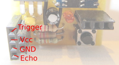
Place a HC-SR04 ultrasonic sensor in your cistern. Build a connection cable between the ultrasonic sensor and the 4-pin header. Be warned: Don’t plug the HC-SR04 directly into the 4-pin header. The pin assignment doesn’t match!
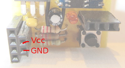
You need also a cable from your solar accu pack to the 2-pin header.
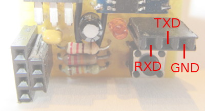
And for downloading the firmware to the ESP8266 you need a cable for the 3-pin header for the serial port. Most people use a USB to serial converter like the FTDI232 to connect the module to the PC.
See the pictures below to find the correct pin assignments.
Flashing the firmware
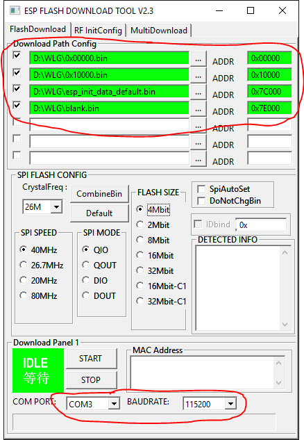 For flashing the firmware into the ESP8266 I suggest the orignal tool from Espressif the manufacturer of the ESP8266 chip. You need to flash the two files from github (0x00000.bin and 0x10000.bin) and the files esp_init_data_default.bin and blank.bin from the bin directory of the Espressif SDK 1.5.2. Start the flash download tool, select the four files for download, adjust your com port and set the download speed. I suggest a baud rate of 115200. The SPI FLASH CONFIG group must not be changed. The flash will be auto detected.
Connect the water level module via the 3-pin header to your USB-to-serial converter and the converter to the PC.
For flashing the firmware the module must enter the download mode. To achieve this do the following in this order:
- Press the START button in the flash download tool
- Hold the micro button on the module down
- Connect the 5V power from the solar accu pack to the 2-pin header. Consider the polarity!
The download should start immediately. Maybe you need to practice this a few times because it must be done in a few seconds. After the download starts you can release the micro button.
The download lasts a few seconds. If it’s finished with success disconnect power, close the download tool and open a serial terminal like Putty or CoolTerm. Adjust the COM port, set the baud rate to 74880 and open/connect the COM port. Then power the water level gauge module on.
If all went good the LED of the module blinks slowly and the module enters the configuration mode automatically. if you find the message
Activating access point 'WaterLevelGauge' and listening at port 1253 ...
in the terminal window you can start with the configuration of your module.
Configuring the water level gauge
After flashing the four files the module goes automatically into the configuration mode because it doesn’t find a configuration. You can also enter the configuration mode manually after powering the module on. To enter the configuration mode power the module on, let the LED flash one time, press the micro button for at least to seconds and the release the micro button. If the module has entered the configuration mode the LED will blink slowly.
The configuration is done by sending a JSON data string via TCP/IP connection to the port where the module is listening. You can send the JSON data via smart phone. I use the free of charge Android app TCP client for the configuration. But it’s up to you, what way you choose to send the data. You need only a Wi-Fi enabled device that’s capable to connect via WPA2 to the Wi-Fi access point, connect to the TCP server socket and send the data string.
Simply connect the Wi-Fi of your smart phone or similar device to the access point „WaterLevelGauge“ that the module provide. For the Wi-Fi connection you need the password „IoT-Wlg!4711#“. In the TCP client app or similar tool you need to connect to the IP 192.168.4.1 port 1253.
Here is an example of the configuration to send:
{
  "SSID": "Your router SSID",
  "Password": "Your router password here",
  "CisternType": 1,
  "CisternRadius": 1000,
  "CisternLength": 2320,
  "DistanceEmpty": 1730,
  "LitersFull": 5853,
  "HostName": "WaterLevelGauge1",
  "DeepSleepPeriod": 600,
  "MinDifferenceToPost": 5,
  "MaxDataAgeToPost": 3600,
  "ThingspeakApiKey": "Your API key here",
  "LogType": 0,
  "LogHost": "-",
  "LogPort": 0
}
Adjust all the settings in the example to your needs.
- SSID: The SSID (the display name) of the router. If the measurement should be posted to Thingspeak the module connects to this router.
- Password: The password for the router
- Cisterntype:
- 1 = the cistern is a horizontal cylinder
- 2 = the cistern is a vertical cylinder
- CisternRadius: The radius in millimeters of the cylinder
- CisternLength: The length of the cylinder in millimeters
- DistanceEmpty: The distance between the HC-SR04 ultrasonic sensor and the water or the bottom of the cistern if the cistern is empty
- LitersFull: The amount of liters in the cistern if the cistern is filled to 100%
- HostName: This name will be set as hostname after the module has connected to the router. Maybe you will distinguish different modules by hostname
- DeepSleepPeriod: The time span in seconds between two measurements. During this time the module consumes low current.
- MinDifferenceToPost: If two measurements are not differ more than this amount of millimeters the data will not be posted to Thingspeak to conserve power
- MaxDataAgeToPost: After this amount of seconds the measurement will always be posted to Thingspeak, even if the MinDifferenceToPost is not reached
- ThingspeakApiKey: The API key of your Thingspeak channel
- LogType: Set to zero unless you need the help of the TcpLogger feature for troubleshooting
- LogHost: Set to „-“ unless you need the help of the TcpLogger feature for troubleshooting
- LogPort: Set to zero unless you need the help of the TcpLogger feature for troubleshooting
Setup a Thingspeak channel
For setup a Thingspeak channel that will work with the Wi-Fi water level gauge you need first register for a free account at Thingspeak. Then you should setup a new channel with three fields. The module will post the following values into the three fields:
- Field1: The water level in centimeters
- Field2: The water level in liters
- Field3: The water level in percent
Troubleshooting with the TcpLogger
If you have problems during the operation of the Wi-Fi water level gauge and you can’t connect a PC via serial connection you have the option to send all the messages that are output to the serial connection via TCP/IP to a program that logs the messages. I’ve written a short C# console program that receives the log and writes it to a file.
using System;
using System.IO;
using System.Net.Sockets;
using System.Text;

namespace TcpLogger
{
	class Program
	{
		static void Main(string[] args)
		{
			StreamWriter writer = File.CreateText("TcpLogger-" + DateTime.Now.ToString("yyyyMMddHHmmss"));
			try
			{
				TcpListener server = new TcpListener(1254);
				server.Start();
				while (true)
				{
					TcpClient client = server.AcceptTcpClient();
					// Read the data stream from the client.
					byte[] bytes = new byte[256];
					NetworkStream stream = client.GetStream();
					bool writeTimeStamp = true;
					while (true)
					{
						int length = stream.Read(bytes, 0, bytes.Length);
						if (length == 0)
						{
							break;
						}
						if (writeTimeStamp)
						{
							writer.WriteLine();
							writer.WriteLine(DateTime.Now.ToString("yyyyMMddHHmmss"));
							writeTimeStamp = false;
						}
						writer.Write(Encoding.ASCII.GetString(bytes, 0, length));
					}
					writer.Flush();
				}
			}
			catch (Exception exception)
			{
				writer.WriteLine(exception.Message);
				writer.WriteLine(exception.StackTrace);
			}
		}
	}
}
To configure the module to send the log to the TcpLogger adjust the configuration and set the parameters accordingly:
- LogType
- 1 = Send log via unencrypted TCP/IP connection
- 2 = Send log via encrypted TLS TCP/IP connection. Maybe this feature is not currently working!
- LogHost: Set to an IP or hostname where the TcpLogger program is listening
- LogPort: Set to the port where the TcpLogger program is listening